Archimate - Layer 2 Network Diagrams in Archi
Jul 23, 15Note: I am going to make many references to Archimate and Archi in this article. You can read up on the Archimate standard at this link: http://pubs.opengroup.org/architecture/archimate2-doc/ and you can read up on Archi (a tool for creating Archimate models and views) at this link: http://www.archimatetool.com/. If you are unfamiliar with network layers you may also need to perform some research on that topic. This turned out to be a longer article than I thought, so I am breaking it into two parts. Layer 2 will be done in this article, Layer 3 in the next. I’ll update this article with a link after I publish that one.
I have been using Archimate for some time now. I primarily use Archi for creating models and views as needed on a day to day basis. I got certified last year after using the standard and various tools for about a year or so and have been using it regularly ever since.
One of the items that has plagued me for some time is how to represent network architecture. Frequently I am working with more conceptual stuff, but when I do want to show networking, what should I do? Interfaces or not? Networks or Communication Paths? Nodes vs Devices? I have made various choices based on need in the past. I thought I would take some time, work through one with more intention, and try to make a few decisions.
An article on packetpushers served as a source of inspiration and also as a source for the sample network diagram. This is a great article that shows how to take config information from network devices and turn it into a layer 3 diagram. It also includes a great example of a Layer 2 diagram.
Link: http://packetpushers.net/how-to-draw-clear-l3-logical-network-diagrams/
These appear to be Visio diagrams, so how should I turn these into Archimate Models? My preference is to be model driven which means elements and relationships come first. This means lists of things. That is what the ‘model’ is basically. Lists of elements and Lists of relationships. There is a very real attraction to dive into the view creation and perform data entry that way, but I think more gets done if you start with the model and move forward. At least I generally feel like I uncover gaps in my assumptions and end up with a more solid model. Normally after creating the elements, I can dive into the relationships if needed to get some kind of work in progress to evaluate.
So let’s start with Layer 2 since that’s all device and ports and such. Should be easier, no?
I’ll use this diagram:
 {width=”672”
height=”768”}
Source: http://packetpushers.net/wp-content/uploads/2012/12/Example-network2.jpg
First let’s see what kind of elements we are going to use. Looking at this picture we have the following unique elements:
- Some Devices
- Lines connecting them
- Some labels on the lines representing different things
- Po1 Labels which seem to be different than the other labels
We’ll map these to the Archimate elements like so:
- Some Devices – We’ll just make these ‘Device’ Elements
- Lines connecting them – We’ll just make these ‘Association’ Relationships
- Some labels on the lines representing different things – We’ll make these ‘Interface’ Elements on the Devices
- Po1 Labels which seem to be different than the other labels – I’m not sure what these are, so we’ll ignore them for now
Why these items? You can look at the definitions for the items on the Archimate standard site.
Let’s make a list of the Archimate Elements. First Devices, and then Interfaces. The interfaces all “belong” to certain devices and do not have unique names, so you will have to list them with a parent.
Devices:

  -----------
  Inet-rtr1
  Inet-rtr2
  Outsw1
  Outsw2
  Fw1
  Fw2
  Csw1
  Csw2
  Asw1
  Asw2
  Asw3
  -----------

Interfaces:

  ----------- -----------
  Parent      Interface
  Inet-rtr1   G0/0
  Inet-rtr2   G0/0
  Outsw1      G1/0
  Outsw1      G1/1
  Outsw1      G1/3
  Outsw1      G1/4
  Outsw2      G1/0
  Outsw2      G1/1
  Outsw2      G1/3
  Outsw2      G1/4
  Fw1         E0/1
  Fw1         E0/2
  Fw1         E0/3
  Fw2         E0/1
  Fw2         E0/2
  Fw2         E0/3
  Csw1        G0/1
  Csw1        G0/2
  Csw1        G0/3
  Csw1        G0/4
  Csw1        G0/5
  Csw1        G0/6
  Csw2        G0/1
  Csw2        G0/2
  Csw2        G0/3
  Csw2        G0/4
  Csw2        G0/5
  Csw2        G0/6
  Asw1        G0/1
  Asw1        G0/2
  Asw2        G0/1
  Asw2        G0/2
  Asw3        G0/1
  Asw3        G0/2
  ----------- -----------
Now the association relationships for the lines:
  ----------- ----------- --------------- ----------- -----------
  Parent      Interface   \< \-- \-- \>   Parent      Interface
  Inet-rtr1   G0/0        x               Outsw1      G1/0
  Inet-rtr2   G0/0        x               Outsw2      G1/0
  Outsw1      G1/0        x               Inet-rtr1   G0/0
  Outsw1      G1/1        x               Fw1         E0/1
  Outsw1      G1/3        x               Outsw2      G1/3
  Outsw1      G1/4        x               Outsw2      G1/4
  Outsw2      G1/0        x               Inet-rtr2   G0/0
  Outsw2      G1/1        x               Fw2         E0/1
  Outsw2      G1/3        x               Outsw1      G1/3
  Outsw2      G1/4        x               Outsw1      G1/4
  Fw1         E0/1        x               Outsw1      G1/1
  Fw1         E0/2        x               Csw1        G0/1
  Fw1         E0/3        x               Fw2         E0/3
  Fw2         E0/1        x               Outsw2      G1/1
  Fw2         E0/2        x               Csw2        G0/1
  Fw2         E0/3        x               Fw1         E0/3
  Csw1        G0/1        x               Fw1         E0/2
  Csw1        G0/2        x               Csw2        G0/2
  Csw1        G0/3        x               Csw2        G0/3
  Csw1        G0/4        x               Asw1        G0/1
  Csw1        G0/5        x               Asw2        G0/1
  Csw1        G0/6        x               Asw3        G0/1
  Csw2        G0/1        x               Fw2         E0/2
  Csw2        G0/2        x               Csw1        G0/2
  Csw2        G0/3        x               Csw1        G0/3
  Csw2        G0/4        x               Asw1        G0/2
  Csw2        G0/5        x               Asw2        G0/2
  Csw2        G0/6        x               Asw3        G0/2
  Asw1        G0/1        x               Csw1        G0/4
  Asw1        G0/2        x               Csw2        G0/4
  Asw2        G0/1        x               Csw1        G0/5
  Asw2        G0/2        x               Csw2        G0/5
  Asw3        G0/1        x               Csw1        G0/6
  Asw3        G0/2        x               Csw2        G0/6
  ----------- ----------- --------------- ----------- -----------
Now, there are some ‘duplicate’ relationships here. We’ll deal with this in a moment. For now we have all of our initial elements and relationships. Let’s go ahead and get these into Archi.
To do this I am going to use the following ‘empty’ model.
<?xml version="1.0" encoding="UTF-8"?>
<archimate:model xmlns:archimate="http://www.archimatetool.com/archimate" name="EmptyModel" version="3.1.0">
<folder name="Business" type="business"/>
<folder name="Application" type="application"/>
<folder name="Technology" type="technology"/>
<folder name="Motivation" type="motivation"/>
<folder name="Implementation & Migration" type="implementation_migration"/>
<folder name="Connectors" type="connectors"/>
<folder name="Relations" type="relations"/>
<folder name="Views" type="diagrams"/>
</archimate:model>
This is basically just the folder structure of the default archi model. I am going to add some elements to it. Archi will add IDs to everything once we open it and save it, so for now each item will be unique just because I’m creating multiple copies. You can add your own IDs if you want and that may be preferable in some instances. If you open a new empty model in Archi and save it with no changes, it will look like this but it will have IDs in it. I just happen to have an empty model that I once upon a time saved so I could insert data. I should also note, now, that the newest version of Archi supports importing CSV files. Those files require a special format and you can look at Archi site if you want to take that route.
First let’s add all of our Devices. To keep things a bit easier to manage, I will put these in their own folder element. These are all Technology items so I am going to put them in the default folder for that.
<?xml version="1.0" encoding="UTF-8"?>
<archimate:model xmlns:archimate="http://www.archimatetool.com/archimate" name="EmptyModel" version="3.1.0">
<folder name="Business" type="business"/>
<folder name="Application" type="application"/>
<folder name="Technology" type="technology">
<folder name="Devices">
<element xsi:type="archimate:Device" name="Inet-rtr1" />
<element xsi:type="archimate:Device" name="Inet-rtr2" />
<element xsi:type="archimate:Device" name="Outsw1" />
<element xsi:type="archimate:Device" name="Outsw2" />
<element xsi:type="archimate:Device" name="Fw1" />
<element xsi:type="archimate:Device" name="Fw2" />
<element xsi:type="archimate:Device" name="Csw1" />
<element xsi:type="archimate:Device" name="Csw2" />
<element xsi:type="archimate:Device" name="Asw1" />
<element xsi:type="archimate:Device" name="Asw2" />
<element xsi:type="archimate:Device" name="Asw3" />
</folder>
</folder>
<folder name="Motivation" type="motivation"/>
<folder name="Implementation & Migration" type="implementation_migration"/>
<folder name="Connectors" type="connectors"/>
<folder name="Relations" type="relations"/>
<folder name="Views" type="diagrams"/>
</archimate:model>
Next we should plug in our interfaces. I am going to adopt the naming convention of [device]interfacename for now so I can keep track of what is related to what.
<?xml version="1.0" encoding="UTF-8"?>
<archimate:model xmlns:archimate="http://www.archimatetool.com/archimate" name="EmptyModel" version="3.1.0">
<folder name="Business" type="business"/>
<folder name="Application" type="application"/>
<folder name="Technology" type="technology">
<folder name="Devices">
<element xsi:type="archimate:Device" name="Inet-rtr1" />
<element xsi:type="archimate:Device" name="Inet-rtr2" />
<element xsi:type="archimate:Device" name="Outsw1" />
<element xsi:type="archimate:Device" name="Outsw2" />
<element xsi:type="archimate:Device" name="Fw1" />
<element xsi:type="archimate:Device" name="Fw2" />
<element xsi:type="archimate:Device" name="Csw1" />
<element xsi:type="archimate:Device" name="Csw2" />
<element xsi:type="archimate:Device" name="Asw1" />
<element xsi:type="archimate:Device" name="Asw2" />
<element xsi:type="archimate:Device" name="Asw3" />
</folder>
<folder name="Interfaces">
<element xsi:type="archimate:InfrastructureInterface" name="[Inet-rtr1]G0/0" />
<element xsi:type="archimate:InfrastructureInterface" name="[Inet-rtr2]G0/0" />
<element xsi:type="archimate:InfrastructureInterface" name="[Outsw1]G1/0" />
<element xsi:type="archimate:InfrastructureInterface" name="[Outsw1]G1/1" />
<element xsi:type="archimate:InfrastructureInterface" name="[Outsw1]G1/3" />
<element xsi:type="archimate:InfrastructureInterface" name="[Outsw1]G1/4" />
<element xsi:type="archimate:InfrastructureInterface" name="[Outsw2]G1/0" />
<element xsi:type="archimate:InfrastructureInterface" name="[Outsw2]G1/1" />
<element xsi:type="archimate:InfrastructureInterface" name="[Outsw2]G1/3" />
<element xsi:type="archimate:InfrastructureInterface" name="[Outsw2]G1/4" />
<element xsi:type="archimate:InfrastructureInterface" name="[Fw1]E0/1" />
<element xsi:type="archimate:InfrastructureInterface" name="[Fw1]E0/2" />
<element xsi:type="archimate:InfrastructureInterface" name="[Fw1]E0/3" />
<element xsi:type="archimate:InfrastructureInterface" name="[Fw2]E0/1" />
<element xsi:type="archimate:InfrastructureInterface" name="[Fw2]E0/2" />
<element xsi:type="archimate:InfrastructureInterface" name="[Fw2]E0/3" />
<element xsi:type="archimate:InfrastructureInterface" name="[Csw1]G0/1" />
<element xsi:type="archimate:InfrastructureInterface" name="[Csw1]G0/2" />
<element xsi:type="archimate:InfrastructureInterface" name="[Csw1]G0/3" />
<element xsi:type="archimate:InfrastructureInterface" name="[Csw1]G0/4" />
<element xsi:type="archimate:InfrastructureInterface" name="[Csw1]G0/5" />
<element xsi:type="archimate:InfrastructureInterface" name="[Csw1]G0/6" />
<element xsi:type="archimate:InfrastructureInterface" name="[Csw2]G0/1" />
<element xsi:type="archimate:InfrastructureInterface" name="[Csw2]G0/2" />
<element xsi:type="archimate:InfrastructureInterface" name="[Csw2]G0/3" />
<element xsi:type="archimate:InfrastructureInterface" name="[Csw2]G0/4" />
<element xsi:type="archimate:InfrastructureInterface" name="[Csw2]G0/5" />
<element xsi:type="archimate:InfrastructureInterface" name="[Csw2]G0/6" />
<element xsi:type="archimate:InfrastructureInterface" name="[Asw1]G0/1" />
<element xsi:type="archimate:InfrastructureInterface" name="[Asw1]G0/2" />
<element xsi:type="archimate:InfrastructureInterface" name="[Asw2]G0/1" />
<element xsi:type="archimate:InfrastructureInterface" name="[Asw2]G0/2" />
<element xsi:type="archimate:InfrastructureInterface" name="[Asw3]G0/1" />
<element xsi:type="archimate:InfrastructureInterface" name="[Asw3]G0/2" />
</folder>
</folder>
<folder name="Motivation" type="motivation"/>
<folder name="Implementation & Migration" type="implementation_migration"/>
<folder name="Connectors" type="connectors"/>
<folder name="Relations" type="relations"/>
<folder name="Views" type="diagrams"/>
</archimate:model>
This is where things get a little fun. You have a decision. Do you want to create relationships in this manner via hardcoding, or do you want to go into the GUI and drag and drop things. Drag and drop takes a little bit, but it may be faster overall. Creating relationships in Archi requires an ID for each element in the XML. You can create IDs that match names, etc to make it easier but it is still a little effort. You can also just open the .archimate file in the tool and save it. It will put generated IDs in there. Then you will have to create relationship elements for each item you want to relate.
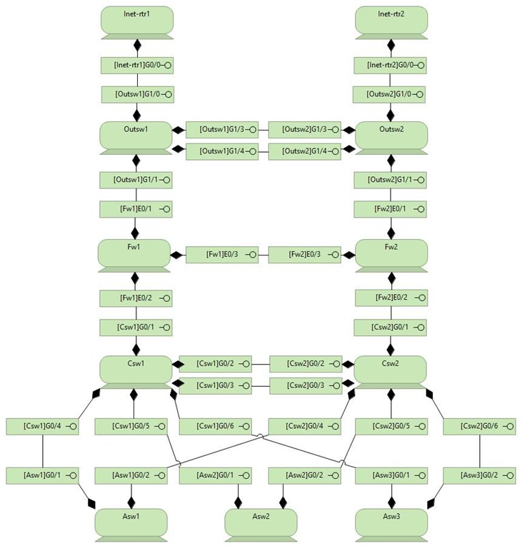
I am just going to use the GUI. To create this I simply opened Archi and dragged all of the elements in the model onto a single canvas. Then I ordered and resized some of the elements as below. Then I drew composition relationships between the devices and their interfaces and I drew association relationships between the interfaces. It’s worth mentioning that association relationships in Archi are directional. Meaning a relationship between A and B is not the same as one between B and A. There is always a source and target. I am not going to worry about that for this exercise so I just structured my view after the source picture and drew relationships from top to bottom and left to right. If I were to do this via hardcoding, I would probably add both association relationships. Here is the first draft.
[
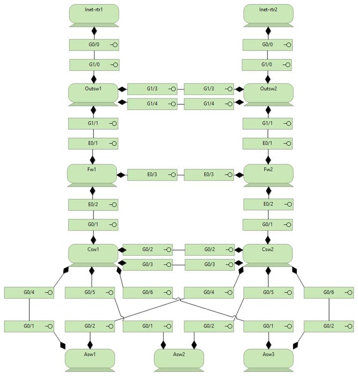
This works fine. You can actually stop here if you like. The data is in the model and you could layer things on top of this if needed. But I’m not sure I like the ‘messiness’ of the parent component being in the name of each interface. What element it belongs to is really handled by the ‘compose’ relationship anyway. Redundancy! So I am going to change the names to make things a bit cleaner like so:

After this, I wanted to get a little closer to existing document. I ended up with the view below.
[
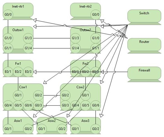
One of the gaps in translating a document like this into Archimate is that you can’t tell what is a router, firewall, etc in the view. You can enter custom user data, which is supported by the standard, if you like. Say I create a field called ‘Type’ and on a Device element I can put Router, Switch, Firewall, PC, Server, etc. I am going to use a different method that I use for servers. I will just create a Device called whatever I want, and I will make these items specializations of that item. Like so:
[
Now this view is very ugly. But the relationships are sound. I can put whatever notes I want on a Router Device without having to put them on each one. I don’t want to show the Device that is specialized in this view, but I want to provide a visual cue, so I am going to simply use color coding and a note. The model doesn’t need visual elements because the data is in the relationships and the elements themselves. I know that ASW3 is a switch because it is a specialization of a device called a switch. But for the view, I need to see some info. Like so:
[![clip_image002[7] clip_image002[7]](http://lh3.googleusercontent.com/-bVa0ooR7V4g/VbFfhl3jK-I/AAAAAAAACCE/58bwhY9pB5o/clip_image002%25255B7%25255D_thumb%25255B8%25255D.jpg?imgmax=800)
And this is our final Layer 2 Diagram. I am not sure what the Po1 sets were, but if they were paired channels, I would simply have the pairing interfaces compose a paired interface and link those. If you are trying this at home and wondering how I got everything to be the same color without clicking on each device, I used the Format Painter on the Palette in Archi. Another quick tip if you need to perform a ton of connections of the same type is to hold SHIFT before you click on the relationship in the Palette. Then you can use it over and over again until you hit ESC or click out of it in some way.
Actually, as a final touch, I normally add some notes and a title to my view. At least the ones that I actually mean people to ‘look at’ rather than one that is a working view for me to model in. Here is my final update.
[![clip_image004[5] clip_image004[5]](http://lh3.googleusercontent.com/-bdjnkRet9ho/VbFfiXzrt4I/AAAAAAAACCc/QPwbfgUDMVs/clip_image004%25255B5%25255D_thumb%25255B4%25255D.jpg?imgmax=800)
The notes are just whatever I thought would be relevant at the time. If I were going to ‘present this’ it is likely I would always put the data back into Visio, PowerPoint, or some other ‘prettier’ tool. But if you need to get the L2 data into your model, this is how I would do it.
This blog post has become longer than I thought it would be, so I am making it Layer 2 only and will do the Layer 3 mapping in another one.
[